The necessary cables, easy to make them yourselves!
For the cables, you have to use shielded audio cable. I have cable lengths of 3 meter in the shack and it works without problems. You will also need some very common electronic parts, which you probably can find in your junkbox : 1 resistor of 100 kOhm, 1 resistor of 1 kOhm, 1 resistor of 2.2 kOhm, 2 diodes 1N4001, 1 transistor BC387 or 2N222A and 1 DB9 or DB25 female connector. You will also need of course two 3.5 mm jack plugs for the connection with your soundcard and a microhone plug for your transceiver (available at hamradio stores, and depending of the model of transceiver you have).Very little experience in soldering is required.
You will need three cables to connect your transceiver to the computer.
The first one will connect your soundcard 'line in' or 'microphone' to the radio RX audio (you can use the 'earphones' on your transceiver). The 'line in' is preferred since it can cope with a higher voltage than the 'microphone' which is much more sensitive, and we don't need that sensitivity at all. Connect the shield of the cable to the radio ground but DO NOT CONNECT THE SHIELD TO THE GROUND OF THE SOUNDCARD!!! If you do so, you may create a ground loop that will make signals transmission complete impossible !
 |
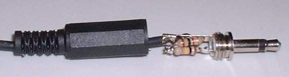
The second one connects your soundcard 'line out' to the radio TX audio. Solder two or the resistors as in the figure below. If you have good 3.5 mm jack plugs for the soundcard end, you can put these in the inside of the plug. Again: connect the shield of the cable to the radio ground but DO NOT CONNECT THE SHIELD TO THE GROUND OF THE SOUNDCARD!!! If you do so, you may create a ground loop that will make signals transmission complete impossible !
 |
 |
The third cable requires a little bit more of effort. It opens the PTT (Push To Talk) circuit of your transceiver so that packets can be sent. AGWPE handles this by sending a signal to the RTS pin of the com port of your PC. This pin number 7 on a DB9 connector or pin number 4 on a DB25 connector. These connectors normally have pin-numbering on it, so it is obvious to know which pin you have to use ...
 |
As with the first cable, I managed to get the complete 'thing' in the DB9 plug. Only be carefull not to make short-circuit, because that will harm your computer com port badly !
 |
Since I had several transeivers in use and several types of TNC (e.g. the soundcard) I used short cables for both the transceiver and the pc end. To make it easy, I used a male DIN 5 plug for the transceiver end and a female DIN 5 plug to make an 'extension cable'. At the PC end the same is done, so a male plug for the TNC or soundcard end and a female plug at the cable end. This has the extra advantage that you can make cables of several lengths, depending on the situation where you want to use them. The DIN 5 pins have all the same meaning, so I can mix and match all equipment as wanted! In my configuration the following pin assigment was made, but you can change it of couse according to your wishes :
pin 1 |
pin 2 |
pin 3 |
pin 4 |
pin 5 |
TX audio |
PTT |
RX audio |
ground |
not used |